Late last year I was putting the cover on my bike (ZXR250C) & somehow managed to snap the indicator. Was pretty annoyed but fixed the problem with some flash glue & black electrical tape only to snap the goddam thing off again a couple weeks later doing the same thing.
Decided I hate indicators that stick out, so I got myself some flush-mounted LED indicators (the bright, visible type) and wired them up, but here's the problem...
When an indicator on my bike is busted and you use the indicator it just stays on - doesn't flash. The LED's are all wired up properly, but when I use the signal they don't flash - they just stay on. Can't figure out what the problem is so before go and tear the bike apart I thought I'd see if anyone here has had any similar problems & could help me out!
Cheers!
P.S. Did a search on the forum and couldn't find much in the way of help...
LED indicator problem
-
Ratmick

- Team Hornet
- Posts: 1931
- Joined: Wed Apr 21, 2004 12:22 pm
- Bike: Other Kawi
- State: Victoria
- Location: Macedon Ranges
Re: LED indicator problem
Hi Cam, welcome to the Forum by the wayCAM wrote:Late last year I was putting the cover on my bike (ZXR250C) & somehow managed to snap the indicator. Was pretty annoyed but fixed the problem with some flash glue & black electrical tape only to snap the goddam thing off again a couple weeks later doing the same thing.
Decided I hate indicators that stick out, so I got myself some flush-mounted LED indicators (the bright, visible type) and wired them up, but here's the problem...
When an indicator on my bike is busted and you use the indicator it just stays on - doesn't flash. The LED's are all wired up properly, but when I use the signal they don't flash - they just stay on. Can't figure out what the problem is so before go and tear the bike apart I thought I'd see if anyone here has had any similar problems & could help me out!
Cheers!
P.S. Did a search on the forum and couldn't find much in the way of help...
This is a common problem with LED blinkers on bikes and cars where there isn't an electronic flasher relay in circuit, just one that relies on the current drawn through the bulbs to heat a bimetal strip. FYI a bimetal strip is two dissimilar metals that have been bonded together lengthwise. As you probably know if you pass a current through any metal it will cause heat and when this occurs the metal will expand. When two dissimilar metals are bonded together and one has different expansion characteristics to the other the strip will bend away from the metal that has the most expansion. This is what occurs inside your flasher relay when you turn the indicators on - the differential heating of the two metals causes the strip to bend and this will open the current path to your blinkers...and the light will go out. With no current flow the strip cools down, and bends back the other way until it makes contact. Now the light comes on until the strip is hot enough to bend and break contact again. The heating/cooling cycle is what causes the indicators to flash (sorry if this is teaching you to suck eggs).
What's happening now with your new indicators is that the current through the LEDs is far smaller than the current that used to be drawn through the bulbs, and there isn't enough heat buildup in the bimetal strip to cause the bending and hence the contacts to open, so yours are staying on.
There are two fixes. The first and most expensive is to put an electronic flasher relay in. These don't rely on current flow. Second and cheaper solution is to place a resistor in the current path which mimics the old resistance of the bulb circuit.
I'm not 100% sure of the resistance required or the exact config of the circuit. Give me a few hours to get dinner for the kids underway and get them off to bed and I'll see if I can find out more info for you.
thks
Mick
Last edited by Ratmick on Sun Feb 25, 2007 8:24 pm, edited 1 time in total.
-
Strika

- VIP MEMBER

- Posts: 8373
- Joined: Tue Feb 01, 2005 8:02 am
- Bike: Yamaha
- State: Victoria
- Location: Melbourne
RM is on the money. As with him, I am unsure as to the resistor required to mimic normal current flow. Any electrical gurus in here?????  Once you sort that the indicators will flash just like normal, all things being equal!
"I hate to advocate drugs, alcohol, violence or insanity to anyone, but they've always worked for me" Hunter S. Thompson.
There are really only two questions in life. 1.Which way do i go? 2.What is the lap record?
There are really only two questions in life. 1.Which way do i go? 2.What is the lap record?
-
Ratmick
- Team Hornet
- Posts: 1931
- Joined: Wed Apr 21, 2004 12:22 pm
- Bike: Other Kawi
- State: Victoria
- Location: Macedon Ranges
Apparently if you put a 5 ohm 20 Watt resistor in series with each LED indicator it'll fool your relay to thinking there is a bulb in circuit. These won't be small  . I can't actually find a single resistor this wattage, you would need two of these in parallel:
http://www.jaycar.com.au/productView.as ... BCATID=782
A downside is that they will get hot and may melt whatever they are touching unless they are held off the meltable bits by some means...
...On this note it may be easier to go the electronic relay unit route .
.
I'm not sure how much room is inside the fusebox of a ZXR250, but you will need something like this:
http://cgi.ebay.com.au/3-pin-Electronic ... dZViewItem
HTH
mick
http://www.jaycar.com.au/productView.as ... BCATID=782
A downside is that they will get hot and may melt whatever they are touching unless they are held off the meltable bits by some means...
...On this note it may be easier to go the electronic relay unit route
I'm not sure how much room is inside the fusebox of a ZXR250, but you will need something like this:
http://cgi.ebay.com.au/3-pin-Electronic ... dZViewItem
HTH
mick
Last edited by Ratmick on Wed Feb 28, 2007 9:21 pm, edited 2 times in total.
-
mike-s

- Apprentice Post Whore :-)
")
- Posts: 6142
- Joined: Sat Aug 07, 2004 5:43 am
- Bike: Suzuki
- State: New South Wales
- Location: Arncliffe, Sydney
- Contact:
Personally i'd build a circuit around a type 555 i-c chip with the circuit tweaked to cycle the bulb at a normal 1-1.1Hz. That'd be fun and a lot cheaper than buying the a/market flasher. just rememberto put in voltage regulation so it doesn't get smoked if the alternator puts out a high voltage.
i certainly wouldnt go using ceramic resistors as they'd introduce one hell of a thermal point of weakness in the whole thing.
i certainly wouldnt go using ceramic resistors as they'd introduce one hell of a thermal point of weakness in the whole thing.

If it hurts, you aren't doing it right.


Ratmick wrote:Apparently if you put a 5 ohm 20 Watt resistor in series with each LED indicator it'll fool your relay to thinking there is a bulb in circuit. These won't be small
http://www.jaycar.com.au/productView.as ... BCATID=782
A downside is that they will get hot and may melt whatever they are touching unless they are held off the meltable bits by some means...
...On this note it may be easier to go the electronic relay unit route
I'm not sure how much room is inside the fusebox of a ZXR250, but you will need something like this:
http://cgi.ebay.com.au/3-pin-Electronic ... dZViewItem
HTH
mick

The only problem with Mick's theory is the resistors have to be in parallel, not in series as in the diagram, as you can see the resisters in that diagram the current will be further limited by the resisters. That diagram would work if you had an electronic flasher timed for bulbs that were flashing too fast, best option get the flasher mentioned,
Cheers.

-
Ratmick
- Team Hornet
- Posts: 1931
- Joined: Wed Apr 21, 2004 12:22 pm
- Bike: Other Kawi
- State: Victoria
- Location: Macedon Ranges
Look again, the diagram shows two resistors in parallel, not seriesBladeBoy wrote:
The only problem with Mick's theory is the resistors have to be in parallel, not in series as in the diagram, as you can see the resisters in that diagram the current will be further limited by the resisters. That diagram would work if you had an electronic flasher timed for bulbs that were flashing too fast, best option get the flasher mentioned,
Cheers.
..but you're right, go the electronic flasher
-
Ratmick
- Team Hornet
- Posts: 1931
- Joined: Wed Apr 21, 2004 12:22 pm
- Bike: Other Kawi
- State: Victoria
- Location: Macedon Ranges
I am chastened, and offer humble apologiesBladeBoy wrote:Mick, I am not talking about the resister network that are in parallel, I am referring to the resistance should be in parallel with the load.
How could putting your resistor network in series with a LED make it draw more current?
Anyway, how about this one (this assumes the LED indicator unit has it's own internal resistor):
- Attachments
-
- Mick is a doofus.
- a-ha!.jpg (10.26 KiB) Viewed 5162 times
WOW, thanks heaps for the help guys - I wasn't expecting such a big response! The LED unit does actually have some resistors in it - I'll have a look at them and see what they are (they're small ceramic ones). I actually just sat an exam today for my 1st year electrical apprenticeship which coversed resistors, so identifying it shouldn't be a problem!
If I were to get the flashing unit off ebay, how would I install if?
I personally like the idea of installing the resistors in parallel, would be soooo much easier!
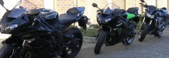
Here's a pic of the bike for those that are curious..... it's actually being put on the market once I get all the fresh parts put on it if anyone in Melbourne is interested! All original ltd ed. fairings, HEAPS of performance mods - sounds insane & easily out runs other 250's!
If I were to get the flashing unit off ebay, how would I install if?
I personally like the idea of installing the resistors in parallel, would be soooo much easier!
Here's a pic of the bike for those that are curious..... it's actually being put on the market once I get all the fresh parts put on it if anyone in Melbourne is interested! All original ltd ed. fairings, HEAPS of performance mods - sounds insane & easily out runs other 250's!
- Attachments
-
-
photomike666
- Apprentice Post Whore :-)
- Posts: 5956
- Joined: Sat Jan 15, 2005 12:01 am
- Bike: ZX10R
- State: Victoria
- Location: Melbourne
- Contact:
If you selling it, get a standard indicator from a wreckers and save yourself lots of hassle.
As for the flasher unit, it should replace the standard relay, which will be a plug and play device under you fairing somewhere - usually seat unit
As for the flasher unit, it should replace the standard relay, which will be a plug and play device under you fairing somewhere - usually seat unit
--------------------------------------------------------------------------------------------------------------
07 ZX10R since new, tracky TBA, KX450F, 87 CR250 restoration, GT MTB - I've got serious thrill issues, dude
07 ZX10R since new, tracky TBA, KX450F, 87 CR250 restoration, GT MTB - I've got serious thrill issues, dude