Hi all,
The saga of the MK II rebuild continues, attacked the wiring last night and discovered that it has a GT750 igniter fitted (part number actually comes up on buykawasaki.com as for a Z750 Spectre or LTD, but (presumably) a wrecker has written GT 750 on the back, so presume they're the same.
If anyone can help, I'd love a) a copy (colour would be perfect) of the wiring diagram so I can see how this is wired up, and b) any pages on the ignition unit itself - may include how to test, and more particualrly the advance curve.
I'vbe no idea whether it worked on the Mk II at any point as the rest of the loom is butchered, but it's been soldered in so I'd assume the connector at least is different ...
Many thanks in advance,
Brian
Kawasaki Sportsbike Riders Club - Australia - Online Forum
Australian Kawasaki Sportsbike Riders Discussion Forum - All Welcome, free and easy to join, just click "register" below - www.ksrc-au.com
Any GT750 owners out there with a workshop manual ?
13 posts
• Page 1 of 1
Any GT750 owners out there with a workshop manual ?
![]() by greenman43 » Sun May 12, 2013 10:24 am
by greenman43 » Sun May 12, 2013 10:24 am
07 ZX10R track 09 ZX6R road/track 93 ZXR750 race 89 GPZ900 project
Do not walk behind me, for I may not be leading
Do not walk in front of me, for I may not be following
Do not walk alongside me, for the path may be narrow
Just piss off and leave me alone
Do not walk behind me, for I may not be leading
Do not walk in front of me, for I may not be following
Do not walk alongside me, for the path may be narrow
Just piss off and leave me alone
-

greenman43 - KSRC Regular

- Posts: 675
- Joined: Fri May 06, 2005 10:01 pm
- Location: Brooklyn NSW
- Bike: ZX6R
- State: New South Wales
Re: Any GT750 owners out there with a workshop manual ?
![]() by bonester » Sun May 12, 2013 9:11 pm
by bonester » Sun May 12, 2013 9:11 pm
Dunno about 750, but the GT550 has two different ignitors and wiring harnesses depending on age. Early ones advance ignition timing with weights and springs like a car distributor, and later ones are done within the ignitor. 750 might be the same and you would need the correct ignitor.
2 X ZRX1200R 4 X ER6N, GT550, 1988 ZX-10, 4 X GPZ250R, 4 X GPZ900R and GPZ750R  Yeah I like Kawasakis.
- bonester
- KSRC Contributor

- Posts: 2075
- Joined: Sun Apr 17, 2005 1:00 pm
- Location: Toowoomba/Ipswich Queensland
Re: Any GT750 owners out there with a workshop manual ?
![]() by greenman43 » Sun May 12, 2013 9:57 pm
by greenman43 » Sun May 12, 2013 9:57 pm
Cheers mate, someone has mounted this GT igniter on a 1980 Z1000 Mk II, hence my confusion !
Brian
Brian
07 ZX10R track 09 ZX6R road/track 93 ZXR750 race 89 GPZ900 project
Do not walk behind me, for I may not be leading
Do not walk in front of me, for I may not be following
Do not walk alongside me, for the path may be narrow
Just piss off and leave me alone
Do not walk behind me, for I may not be leading
Do not walk in front of me, for I may not be following
Do not walk alongside me, for the path may be narrow
Just piss off and leave me alone
-
greenman43 - KSRC Regular
- Posts: 675
- Joined: Fri May 06, 2005 10:01 pm
- Location: Brooklyn NSW
- Bike: ZX6R
- State: New South Wales
Re: Any GT750 owners out there with a workshop manual ?
![]() by bonester » Sun May 12, 2013 10:00 pm
by bonester » Sun May 12, 2013 10:00 pm
If it is a springs and weights type it should work I'd imagine.
2 X ZRX1200R 4 X ER6N, GT550, 1988 ZX-10, 4 X GPZ250R, 4 X GPZ900R and GPZ750R Yeah I like Kawasakis.
- bonester
- KSRC Contributor
- Posts: 2075
- Joined: Sun Apr 17, 2005 1:00 pm
- Location: Toowoomba/Ipswich Queensland
Re: Any GT750 owners out there with a workshop manual ?
![]() by greenman43 » Sun May 12, 2013 10:15 pm
by greenman43 » Sun May 12, 2013 10:15 pm
Appreciate the input, but I'm looking to see the wiring diagram and specs so I can try to establish for myself, rather than bodge it up to my new wiring loom and see if it works, hence my request for a workshop manual.
Cheers,
Brian
Cheers,
Brian
07 ZX10R track 09 ZX6R road/track 93 ZXR750 race 89 GPZ900 project
Do not walk behind me, for I may not be leading
Do not walk in front of me, for I may not be following
Do not walk alongside me, for the path may be narrow
Just piss off and leave me alone
Do not walk behind me, for I may not be leading
Do not walk in front of me, for I may not be following
Do not walk alongside me, for the path may be narrow
Just piss off and leave me alone
-
greenman43 - KSRC Regular
- Posts: 675
- Joined: Fri May 06, 2005 10:01 pm
- Location: Brooklyn NSW
- Bike: ZX6R
- State: New South Wales
Re: Any GT750 owners out there with a workshop manual ?
![]() by Eastoe » Tue May 14, 2013 12:42 pm
by Eastoe » Tue May 14, 2013 12:42 pm
I tried to upload a picture from the Z750/GPZ750 manual to see if it is the same as you are after but the site thought about it for too long and wouldn't take it. Not sure if the ignition is the same as you are after but I allways thought the 750GT engine was a Z or GPZ.
- Eastoe
- KSRC Member

- Posts: 102
- Joined: Fri Feb 10, 2006 6:11 pm
- Location: Casula NSW
- Bike: GPz750
- State: New South Wales
Re: Any GT750 owners out there with a workshop manual ?
![]() by h.b.bear » Tue May 14, 2013 6:37 pm
by h.b.bear » Tue May 14, 2013 6:37 pm
If you have had no luck PM me your address and I will post a manual down to you.dont ask for photo copy,scan and email as I have enough trouble trying to set the alarm on my phone  but I will lend you my manual.Cheers Garry
- h.b.bear
- KSRC Contributor
- Posts: 1175
- Joined: Wed Oct 27, 2010 2:21 pm
- Location: Tamworth NSW
- Bike: ZRX
- State: New South Wales
Re: Any GT750 owners out there with a workshop manual ?
![]() by greenman43 » Tue May 21, 2013 10:50 pm
by greenman43 » Tue May 21, 2013 10:50 pm
Eastoe wrote:I tried to upload a picture from the Z750/GPZ750 manual to see if it is the same as you are after but the site thought about it for too long and wouldn't take it. Not sure if the ignition is the same as you are after but I allways thought the 750GT engine was a Z or GPZ.
Thanks Richard, I'm not really sure; I'd imagine a GT engine is a re-tuned GPZ / Z unit, so perhaps it is the same igniter (especially if the advancer is mechanical ala old Z900 / 1000, so no advance curve in the igniter).
Cheers,
Brian
07 ZX10R track 09 ZX6R road/track 93 ZXR750 race 89 GPZ900 project
Do not walk behind me, for I may not be leading
Do not walk in front of me, for I may not be following
Do not walk alongside me, for the path may be narrow
Just piss off and leave me alone
Do not walk behind me, for I may not be leading
Do not walk in front of me, for I may not be following
Do not walk alongside me, for the path may be narrow
Just piss off and leave me alone
-
greenman43 - KSRC Regular
- Posts: 675
- Joined: Fri May 06, 2005 10:01 pm
- Location: Brooklyn NSW
- Bike: ZX6R
- State: New South Wales
Re: Any GT750 owners out there with a workshop manual ?
![]() by greenman43 » Tue May 21, 2013 10:53 pm
by greenman43 » Tue May 21, 2013 10:53 pm
h.b.bear wrote:If you have had no luck PM me your address and I will post a manual down to you.dont ask for photo copy,scan and email as I have enough trouble trying to set the alarm on my phone
Thanks for the very kind offer Garry, just got the factory manual for my bike today (the old Kawa manuals are beautiful reading, lovely oil-proof glossy pages, a how-it-works section, and colour wiring diagrams).
If you're ok with it, I'm thinking that it might be simpler if I describe to you what my manual looks like, and you see how it compares to the GT - there are really only two sections I need, where the wiring from the igniter goes (and the colours), and the section on testing the igniter (resistance readings across terminals).
Cheers,
Brian
07 ZX10R track 09 ZX6R road/track 93 ZXR750 race 89 GPZ900 project
Do not walk behind me, for I may not be leading
Do not walk in front of me, for I may not be following
Do not walk alongside me, for the path may be narrow
Just piss off and leave me alone
Do not walk behind me, for I may not be leading
Do not walk in front of me, for I may not be following
Do not walk alongside me, for the path may be narrow
Just piss off and leave me alone
-
greenman43 - KSRC Regular
- Posts: 675
- Joined: Fri May 06, 2005 10:01 pm
- Location: Brooklyn NSW
- Bike: ZX6R
- State: New South Wales
Re: Any GT750 owners out there with a workshop manual ?
![]() by Gosling1 » Wed May 22, 2013 9:00 pm
by Gosling1 » Wed May 22, 2013 9:00 pm
Brian - what you should have is this:
From the igniter unit, there are 2 sets of leads coming out. One plug is for the 4 wires coming up from the 2 igniter coils (pick-up coils) on the end of the crank. These should be blue/black and yellow/red. I am pretty sure the blue/black wires are from the l/h igniter coil and fire 1&4, the yellow/red wires are from the r/h side pickup, and fire the #2&3 coils.
The other lead from the igniter unit goes up to the ignition coils - well, 3 of the 4 wires do but you can't see this once you plug into the main harness . The colours coming out of the unit are green, red/yellow, black and black/yellow. The black/yellow is an earth for the igniter unit and does not end up anywhere near the ignition coils. The black lead goes to the #1/4 coil, the green lead goes to the #2/3 coil. The red/yellow lead is the +12v feed to both coils - where the small lead from the igniter unit plugs into the main harness, this lead changes colour to plain red.
Hope that helps - the GT motor is just the same as far as the basics go.
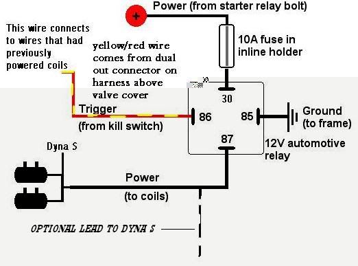
One good mod to do to these old battery/coil systems, is wiring in a normal 12v Bosch or Hella relay into the power supply for the coils. This ensures a good solid +12v power to the coils, instead of the power coming through the wiring harness to the ignition switch then through the kill switch and back into the wiring harness before being plugged into the coils.
This is what the wiring diagram looks like - its dead easy to knock this up and it makes a big difference to starting and general running.

From the igniter unit, there are 2 sets of leads coming out. One plug is for the 4 wires coming up from the 2 igniter coils (pick-up coils) on the end of the crank. These should be blue/black and yellow/red. I am pretty sure the blue/black wires are from the l/h igniter coil and fire 1&4, the yellow/red wires are from the r/h side pickup, and fire the #2&3 coils.
The other lead from the igniter unit goes up to the ignition coils - well, 3 of the 4 wires do but you can't see this once you plug into the main harness
Hope that helps - the GT motor is just the same as far as the basics go.
One good mod to do to these old battery/coil systems, is wiring in a normal 12v Bosch or Hella relay into the power supply for the coils. This ensures a good solid +12v power to the coils, instead of the power coming through the wiring harness to the ignition switch then through the kill switch and back into the wiring harness before being plugged into the coils.
This is what the wiring diagram looks like - its dead easy to knock this up and it makes a big difference to starting and general running.

".....shut the gate on this one Maxie......it's the ducks guts !!............."
-
Gosling1 - Team Donut

- Posts: 13823
- Joined: Mon Jun 20, 2005 9:30 pm
- Location: Anarchy Road
- Bike: Z900
- State: ACT
Re: Any GT750 owners out there with a workshop manual ?
![]() by greenman43 » Sun May 26, 2013 9:17 pm
by greenman43 » Sun May 26, 2013 9:17 pm
Thans hugely Gos, some great info there - plenty for me to tinker with.
At the moment I'm elbows-deep in carb part, having stripped them down today and begun to clean them up. Geez, the old VMs are a lot simpler than the Keihn FCRs I've been used to working on !
Cheers,
Brian
At the moment I'm elbows-deep in carb part, having stripped them down today and begun to clean them up. Geez, the old VMs are a lot simpler than the Keihn FCRs I've been used to working on !
Cheers,
Brian
07 ZX10R track 09 ZX6R road/track 93 ZXR750 race 89 GPZ900 project
Do not walk behind me, for I may not be leading
Do not walk in front of me, for I may not be following
Do not walk alongside me, for the path may be narrow
Just piss off and leave me alone
Do not walk behind me, for I may not be leading
Do not walk in front of me, for I may not be following
Do not walk alongside me, for the path may be narrow
Just piss off and leave me alone
-
greenman43 - KSRC Regular
- Posts: 675
- Joined: Fri May 06, 2005 10:01 pm
- Location: Brooklyn NSW
- Bike: ZX6R
- State: New South Wales
Re: Any GT750 owners out there with a workshop manual ?
![]() by Gosling1 » Sun May 26, 2013 10:38 pm
by Gosling1 » Sun May 26, 2013 10:38 pm
no probs mate, have fun with the carbs
".....shut the gate on this one Maxie......it's the ducks guts !!............."
-
Gosling1 - Team Donut
- Posts: 13823
- Joined: Mon Jun 20, 2005 9:30 pm
- Location: Anarchy Road
- Bike: Z900
- State: ACT
Re: Any GT750 owners out there with a workshop manual ?
![]() by greenman43 » Sun May 26, 2013 10:54 pm
by greenman43 » Sun May 26, 2013 10:54 pm
Oooh yes, that white vinegar is good stuff
Cheers,
Brian
Cheers,
Brian
07 ZX10R track 09 ZX6R road/track 93 ZXR750 race 89 GPZ900 project
Do not walk behind me, for I may not be leading
Do not walk in front of me, for I may not be following
Do not walk alongside me, for the path may be narrow
Just piss off and leave me alone
Do not walk behind me, for I may not be leading
Do not walk in front of me, for I may not be following
Do not walk alongside me, for the path may be narrow
Just piss off and leave me alone
-
greenman43 - KSRC Regular
- Posts: 675
- Joined: Fri May 06, 2005 10:01 pm
- Location: Brooklyn NSW
- Bike: ZX6R
- State: New South Wales
13 posts
• Page 1 of 1
Return to Classic Kawi Discussion
Who is online
Users browsing this forum: No registered users and 5 guests